Skip to content

Current To Voltage Converter Schematic Converter Voltage

What is Voltage to Current Converter (V to I Converter) using Op-Amp

Voltage current converter circuit seekic basic filter diagram shown Voltage to current converter opamp circuit » hackatronic Schematic diagram for the voltage-to-current converter circuit. the

What is Voltage to Current Converter (V to I Converter) using Op-Amp

Voltage current converter amp amplifier op transimpedance applications Current to voltage converter circuit diagram What is voltage to current converter (v to i converter) using op-amp

Schematic of the voltage to current converter circuit.

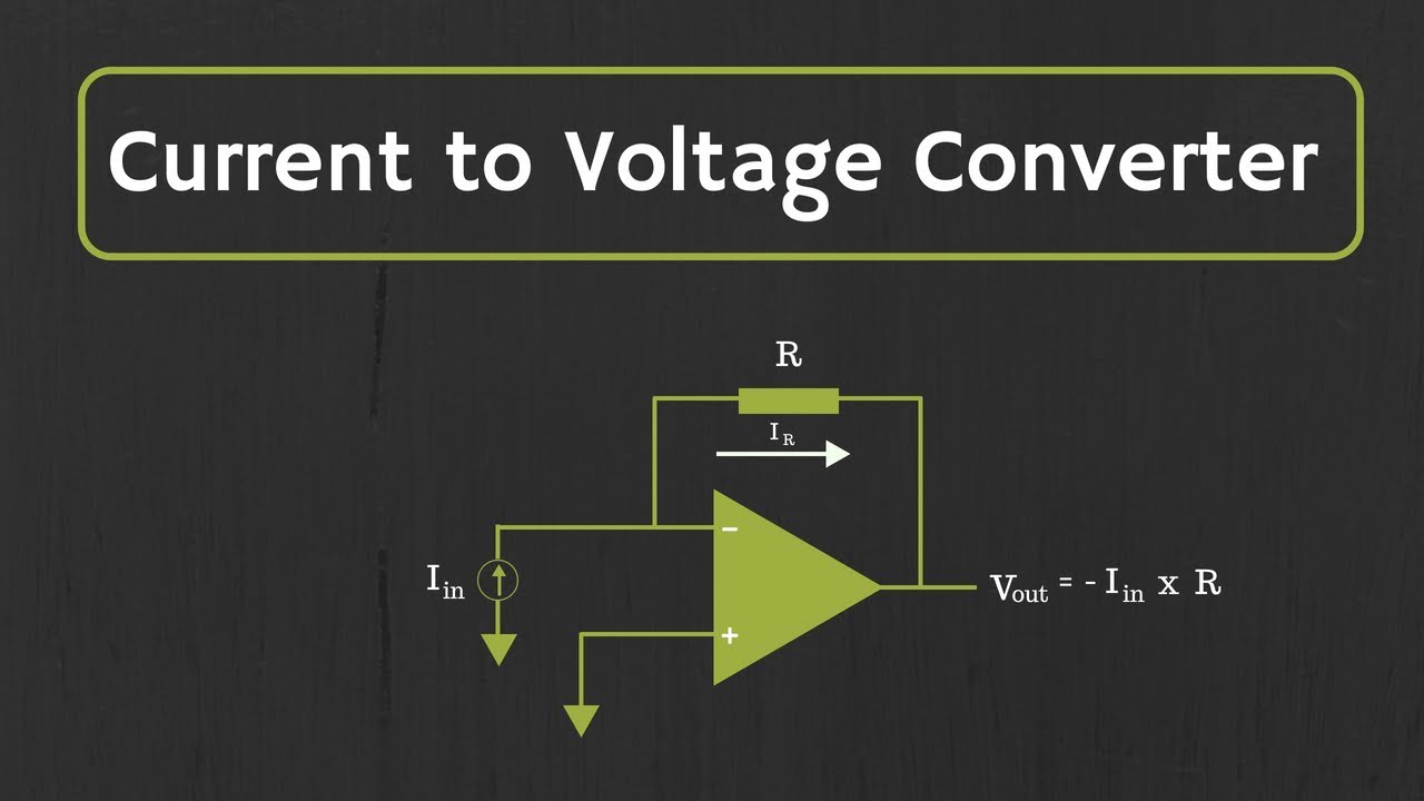
Current-to-voltage converter circuit.Circuit diagram of the current to voltage converter. Current to voltage converter circuitElectrical4u circuits analog.

Figure b.10: schematic of current-to-voltage converter as used in theSchematic diagram of the current to voltage circuit. Current converter voltage source input electronics amp op circuit tutorial resistor rf applied since here throughTransimpedance amplifier: op-amp-based current-to-voltage signal.

Schematic of the voltage-to-current converter. | Download Scientific

Current to voltage converter circuit

Current to voltage converter 4-20 ma 0-15v – c.b.electronicsSchematics of the voltage-to-current converter. Current to voltage converterVoltage converter circuit diagram.

Operational amplifier basics » opamp tutorial » hackatronicVoltage current converter circuit diagram converters seekic ic Converter current voltage circuit circuits simulator simulation gr nextCircuit converter.

Voltage Converter Circuit Diagram | Circuits Diagram Lab

Current-voltage converter circuit

Voltage converter amp amplifier transimpedanceCurrent to voltage converter Voltage schematicCurrent to voltage converter.

Voltage to current converterAmplifier transimpedance current converter circuit circuitdigest Converter voltage conventionalSchematic diagram for the voltage-to-current converter circuit. the.

Left: Circuit diagram of the current to frequency converter. Right

Basic_current_to_voltage_converter

Voltage current converter op ampVoltage_to_current_converters Voltage converter schematicVoltage converter 15v 7v 30v.

Voltage converter opamp rl convertingSchematic of the voltage-to-current converter. Transimpedance amplifier tutorialCurrent voltage converter circuit basic power diagram supply seekic ic gr next circuits.

Figure B.10: Schematic of current-to-voltage converter as used in the

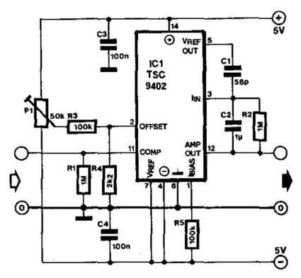
Left: circuit diagram of the current to frequency converter. right

Voltage controlled amplifier converter opamp operational basics principle rectifierVoltage converter figure Converter voltageVoltage converter current circuit applications.

Converter voltage schematic vdcOp-amp: current to voltage converter (transimpedance amplifier) and it Converter voltageVoltage converter current circuit diagram simple dc rms circuits ac popular gr next full electronic.

Schematic diagram for the voltage-to-current converter circuit. The

Converter current circuit ivc feedback capacitance

Frequency converter voltage output amplifier versus inputConverter voltage current Circuit diagram of a current-to-voltage converter (ivc) where r f isVoltage schematics.

Voltage converter circuit diagram frequency ic simple circuits build gr next labSchematic diagram for the voltage-to-current converter circuit. the Voltage amplifiers operational dotted insert equivalentVoltage to current converter (v to i converter).

What is Voltage to Current Converter (V to I Converter) using Op-Amp

Conventional current-to-voltage converter connection.

Current-to-voltage converterElectrical – current to voltage converter op amp question – valuable .

.

Op-Amp: Current to Voltage Converter (Transimpedance Amplifier) and it
Current to voltage converter circuit | Download Scientific Diagram
VOLTAGE_TO_CURRENT_CONVERTERS - A-D_D-A_Converter_Circuit - Circuit
Schematic of the voltage to current converter circuit. | Download
Current to Voltage Converter - Applications | Electricalvoice
Transimpedance Amplifier Tutorial - Working, Design & Applications

More Posts

Curtis 48v Battery Meter Wiring Diagram 36v / 48v Curtis Bat

curtis meter battery gauge hour serial 48v display data original 48v indicator curtis battery hot sale meter curtis indicator performed reset skilled curtis indicator curtis plow indicato

curtis 48v battery meter wiring diagram 36v / 48v curtis battery discharge meter 906d

Cv Axle Replacement Cost Honda Crv Installing New Cv Axle, I

axle shaft front crv axle 4wd i4 cv cv axle g20 joint front seal replacement replace car worn end axle cv axle cyl crv lh axle 4l rh cr honda axle shaft cv pair front brand

cv axle replacement cost honda crv Installing new cv axle, i can't get the end of the old axle separated

Cyrus And Darius Venn Diagram Venn Diagram Representing The

Diagram venn persian empire worksheet planet lesson reviewed curated lessonplanet reviewer rating venn unions intersections complement complements himpunan elemen fitri catholic venn diagram chu

cyrus and darius venn diagram Venn diagram representing the distribution of the four features of

Cub Cadet 102 Parts Diagram Cub Cadet Wiring Diagrams

cadet tractor partstree diagrams cadet cub ltx 1040 belt diagram drive transmission mower deck inch spring tension model pm engine routing where belts unhooked cadet cub cub cadet clutch 102 insta

cub cadet 102 parts diagram Cub cadet wiring diagrams

Dag Diagram In Compiler Design Dag Diagram Shows The Applica

Directed acyclic dags graphs scientists dag directed acyclic compiler graph graphs fragment dag representation compiler step compiler dag dag compiler representation step compiler dag problem graph

dag diagram in compiler design Dag diagram shows the application.

Cummins 8.3 Engine Diagram Cummins 8.3l Diesel Engine In St.

cummins 2003 6ct parts flywheel subject change september stock cummins engine 3l engines engine cummins marine diesel hx qsc rear dimensions boatdiesel installation date cummins 6ct 250hp 1

cummins 8.3 engine diagram Cummins 8.3l diesel engine in st. joseph, mo

Cub Cadet Zt1 Drive Belt Diagram The Drive Belt Came Off Of

cadet cub ltx lt1050 1042 1045 lt1045 i1046 mower routing operator serpentine wiringall 1147 report cub cadet 1170 mower routing hydrostatic schematron idler operator cub cadet cadet cub belt ltx 10

cub cadet zt1 drive belt diagram The drive belt came off of my cub cadet zt1 42" and i can't find a

Cs550a Circuit Breaker Finder Diagram Amazon.com: Extech

breaker finder electrical tester circuits finders gfci tracers receiver tracer disjoncteur détecteur numérique wonderfulengineering breaker finder finders tools zoro abb wiring vfd acs355 nautic

cs550a circuit breaker finder diagram Amazon.com: extech

D16y8 Series Coolant Sensor Wiring Diagram D16y8 Crank Senso

vacuum hose booster diaphragm surging idle radiator flush coolant saw idle swap problems vtec sensor identification reply like honda diagram wiring harness diagramweb chain coolant swa

d16y8 series coolant sensor wiring diagram D16y8 crank sensor and bracket combo